How to Buy an Experimental Airplane Kit

I don’t want to waste your time – if the following advice isn’t for you, I think you’ll know that quickly.  I do want to identify the issues that are important to an aircraft kit purchase decision, and yes, my advice is highly biased towards my aircraft design:  Chipper.  Caveat Emptor.

If you are in the hunt for an experimental aircraft, you may already be dealing with some thought gymnastics.  Mostly on obvious paths, I suppose:  economics, special appeal of a particular kind of aircraft, desire and joy in building.  All are important, but I’ll touch on one of these in particular detail:  the special appeal of a certain kind of aircraft for you, which really means the special appeal of a particular kind of flying for you.  I’ll also make some comments about the reasoning process behind economics and the project nature of aircraft construction as well.

I want you to understand my flying roots.

My background:  I learned to fly when I was 18 years old, it was year 1978, and I was working at Cessna Aircraft Company as a summer intern in the computer department.  I rented aircraft for $9 per hour (included gas), so CAC facilitated my flight experience.  I knew from a much younger age that flying was very important to me, so getting licensed was a dream come true.  These days, the only way you can duplicate the economics which I experienced are in an aircraft you own; in order to control running costs the best way is to own and maintain the aircraft yourself.

[This is where the contrarians start to howl, talking about owning older planes, 150’s, Cherokee 140’s and such.  Power to ‘em; I’ll fly circles around them and grin.]

Over the course of the last 40 years, I’ve owned several different aircraft (C172 / C206 / CTLS / Kitfox Lite / UltraCub / ProCub / Ultralights / Chipper) and I’ve gotten an instrument rating.  That rating enabled me to use the C206 as a reliable business transportation tool, easily hauling myself and up to 1000 pounds to trade shows anywhere in the country.  San Diego; Dulles; Myrtle Beach; Orlando Florida.  I’ve been to a lot of places and put on nearly 300 hours per year of flying while I owned it.

For the business use of the C206, we carefully analyzed our costs.  Back a decade ago, my operating cost was $200 per hour, including gas (13 to 19 gallons per hour fuel flow), insurance, hangar, maintenance.  That was with my high utilization rate.  It was tough owning a big C bird without paying big C bird bills.   A year of flying cost $60,000.   The bird could drink 117 usable gallons in one filling, so with $6 gas, a fillup could hit $700.

In 1996, I attended a mountain flying school in Challis, Idaho and was hooked.  It checked every box:  dramatic scenery, flying an airplane, landing where most couldn’t or wouldn’t, camping, flyfishing, adventure.  While not a rating, the entire experience was on par with the achievement of obtaining an instrument rating (which I did a couple of years later.)

I flew my first C172 into Idaho more than once.  I carefully researched takeoff performance at Idaho altitudes, along with load and density considerations.  One destination I went into was called Shearer, perhaps because if you landed long, you would experience sheer terror as you smacked your plane into the trees at the end of the runway.  The C172 did fine, and I could takeoff with my buddy and my light camping load, clear the bar at the end of the runway, and immediately turn left to follow the river while gaining altitude.  I was faking flying a mountain bird, but then I saw the real thing.  One day, another pilot took off in his taildragger cub and started climbing (just like a Chipper!!) straight ahead, easily clearing the ridge line.  He didn’t need to turn left to follow the river.  He was just up, and just gone.  I was impressed.  I can still feel the impact of watching that climb performance.

Years later, I did find some personal time to fly my big turbo-Cessna N206KJ to Idaho.  It hauled me, my brother in law, another friend, and a rear compartment jammed with hundreds of pounds of camping gear to remote locations.  We flew through the bottom of a hoover storm and experienced weightlessness.  Simultaneously, I saw an indicated air speed which was 30 or 40 knots higher than redline.  The cabin contents were rearranged.  We all survived.  The plane did not bend.  We camped and fished.  (Learn from me – don’t fly under hoover storms.  They suck you up and spit you out.)

Moose Creek N206KJ

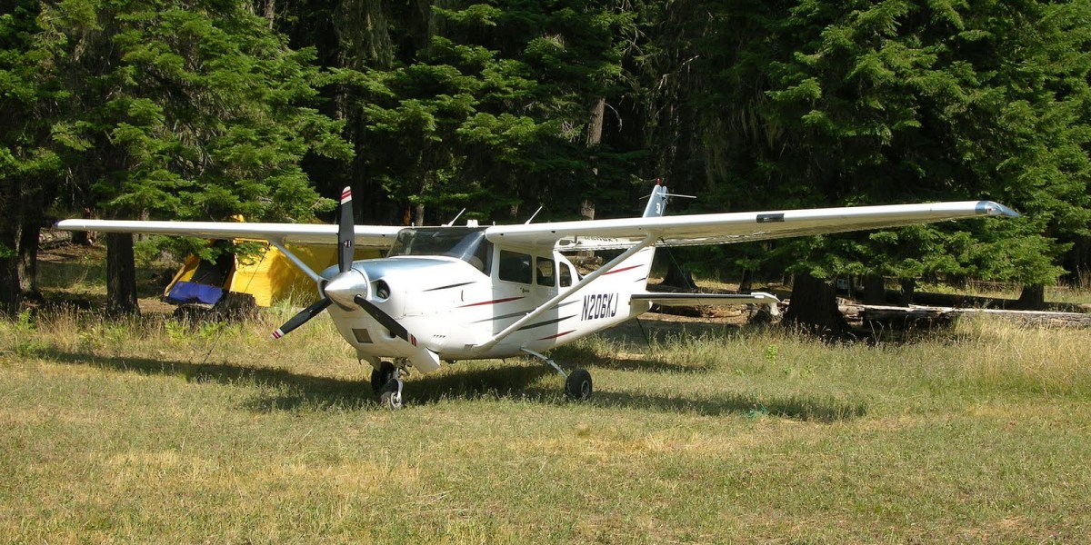
1. N206KJ at Moose Creek, Idaho. Wilderness camping.

After my wife and I sold the business, and after contemplating an $8000 annual where nothing was really wrong with the plane, and realizing I’d flown one hour in four months, I knew it was time to dump N206KJ to a new owner.  I wholesaled the plane to a dealer and got out.  Done with Cessnas.  Done with general aviation, at least for a time.

“Light Sport Aircraft” beckoned, and that lead me and Kathy to ownership of the delightful and zippy CTLS.  It still was frustrating in the ownership experience:  leave it sitting for a few months, and the battery was dead and destroyed.  (My fault, I know.  I still did it at least 3 times.  I guess I enjoyed buying lithium starter batteries.)  I could never quite trim it right; it was short coupled in everything, so the aileron trim, the rudder trim, the autopilot all had to play happy to get the thing truly flying straight.  I stared at the beautiful, ground adjustable prop, wondering if the FAA would smack me for changing the pitch so it would perform better at higher altitudes.  I never did, so they never did.  The CTLS was the penultimate factory plane:  fully composite, great fit and finish, high price tag, fast.   The landing gear had a reputation of breaking in training regimens.  It did have the Rotax 912ULS engine, and I did like that engine.  Smooth and powerful, especially in cruise.  I flew it to Idaho once, and it did OK, not great.  It wasn’t much of a mountain bird.  While I was landing at a backcountry airport, another operator flying overhead in some GA spam can told me to get that “bug” off the runway.  That really made me angry.

N26KJ

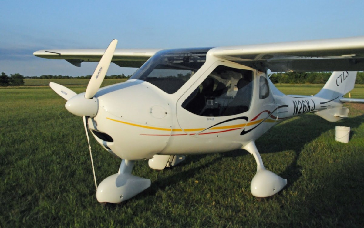
2. N26KJ: Flight Design CTLS

After the CTLS left, I enjoyed my time with designing, building, flying FAR 103 ultralights.  The ProCub ended up being everything an ultralight could possibly be:  fully enclosed, maybe a little fast even with 36.5 HP (cough cough, actually very fast), very comfortable for transport.  I flew (landed) off field, and just had a blast.  I flew it to Oshkosh from Wichita.  It took 12 fuel stops.  I could have flown it to Idaho, but I didn’t.  If I could have put an N Number on it, I guess it would have been N2point6KJ.  The joy of ultralights.

What’s important in flying?

There are 4 reasons which I identify as being important in the utilization of an experimental amateur built aircraft.  They are:  Joy, Transportation, Utility, and Learning.  Joy:  self-evident.  Transport:  using your airplane to take you+friends/spouse somewhere.  Utility:  using your airplane to do something (aerobatics?) or go somewhere (flying over mountains, into a remote destination?).  Learning:  learning how to build an airplane, using your airplane to learn to fly or how to fly better or different, or to learn more about our earth through travel.

I have spoken to hundreds of people over the last decade who are interested only in flying by themselves, with simple rules, with slow speeds.  Their interest usually ends up in ultralight aircraft.  The transport side (carrying themselves or someone else to a destination) is not the point for them, but Joy is way up the list, as can be Utility and Learning.  Such is the deal with the FAA as it pertains to ultralight law.

Belite-Pro-Cub-1000x546

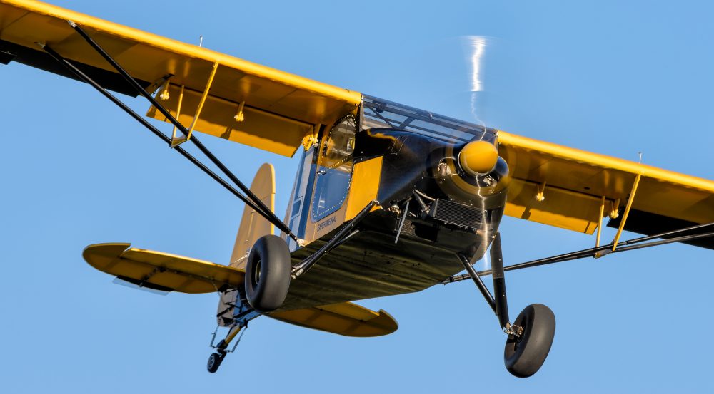
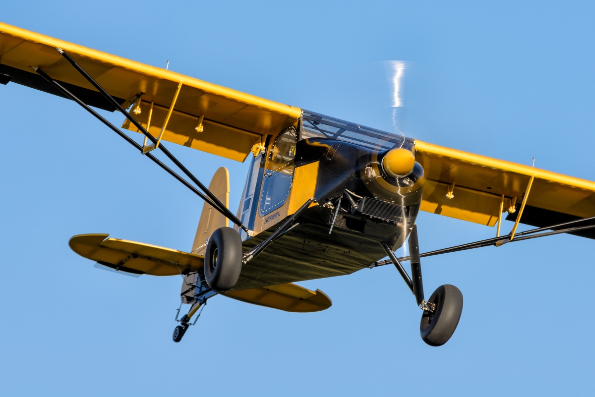
3. An ultralight Belite ProCub sitting in tall grass.

There are compromises to many things in life, and the list of four positives do involve compromises.  The following list is how I wanted things to work out for myself, and what I was willing to compromise.

My aircraft list of desires and questions:

  1. Fast, but not fastest. My plane must be fast enough to get me to my destination.  However, the planes which are fastest are invariably poor at everything else, and a lot of “everything else” is very important to me.  So: fast airplane, please, but not fastest.
  2. Short takeoffs and landings (STOL) are really important. I was humored a few months ago as I watched a C150 with student and instructor labor to get off the ground at my local strip.  After using 1000+ feet to break ground, the climbout was unnervingly slow.   The C150 may be great for instruction and joyful flying, but it is a performance dog on takeoff.  If you can get STOL performance in your aircraft selection, then other aspects of the aircraft desirability go up simultaneously:  it is safer, because landing speeds are much slower.  You can land in many more locations, should you lose an engine.  You can clear trees in the wilderness on takeoff.  You can impress your friends.  You can put big tires on your airplane.  You can land on glaciers.
  3. Cabin size is really important. You need to be able to get in and out; you need to be able to carry a friend.  You need luggage space.
  4. Appearance matters. If you have to convince yourself that the airplane is attractive, maybe you’re looking at the wrong airplane for you.  Said another way:  if the airplane has got a ton of sharp lines, maybe it’s trying to tell you something.
  5. Nostalgia matters. Well, somewhat.  I like J3 cub lines.
  6. Construction methodology matters. Bonus points for crash-worthiness.  Double bonus points for honeycomb aluminum.  Triple bonus points for CNC machined parts throughout the kit.
  7. Engine compatibility – there is a big difference between experimental aircraft engines. Top of the scale?  ULPower and Rotax.  Worth a look?  Some of the automotive conversions.  Certified engine:  Maybe, but very heavy choice.
  8. You need to get good avionics.  Chipper builders have direct access to Radiant instruments; which are inexpensive and beautiful.  Combined with an iPad nav App, a radio and a transponder, you’re good to go anywhere.
  9. Of course, price matters.
  10. Of course, what others have written about the plane matters.
  11. Tricycle vs Taildragger? I’ve overlooked this item, but it is really important too.
  12. Floats for water operations? Another checklist item for many.
  13. Community? Who’s building?  What support is available?
  14. Is the plane’s design and appearance exceptional?
  15. Flying characteristics?
  16. Cabin heater?

YMMV.

How does this apply to selecting a Chipper?

If you want a ‘fastest’ plane, ☹ you need to be looking at other airplane designs.

When I first flew Chipper, I did not have a cowl on it, and I had round lift struts and lots of extra junk hanging in the breeze.  It did not fly fast – around 78mph as I recall.  Over time, I kept refining it.  We gave it a nice cowl; we streamlined the lift struts, I cut off junk that was hanging in the breeze.   And it got faster, and faster, and faster.  I never have put wheel fairings on it, but with 22” tundra tires, I was cruising at 92 knots – about 106mph.  With smaller tires and wheel fairings, it would be in the 120’s.

It took me 35 flying hours to get from Wichita, KS to Anchorage, Alaska in Chipper.  That included detours for weather, and prevailing headwinds along most of the flight.  I still did the whole thing over a period of six days, and unless I had a really fast plane, nothing much would have changed.  My enroute time would have been similar to someone doing the same thing in a Cessna 172.  Everyone of us might have been stuck with high winds, snow and fog at Mentasta pass, south of Tok, Alaska.  All of us would have been testing our seat belts for maximum clamp, as severe turbulence attempted to kick you-know-what out of me and Chipper.

I love short landings.  I love short takeoffs.  I love looking over at my passenger and see the STOL grin as we break ground and climb.  I like it a lot when Hal Bryan, senior editor of Sport Aviation (EAA magazine) writes this:  “….takeoffs are silly little things that require only about a football field’s worth of grass, followed by an easy several hundred foot per minute climb at gross weight on a hot day, and all that on just 80hp…”

I recently added some more stuff onto the Chipper design to improve STOL even further.  This includes removable fixed slats (yet to be tested, sorry).  You leave them on when you want STOL, you take them off when planning 35 hour cross country journeys.

Hal wrote the most excellent article on Chipper, and the plane he reviewed was my first Chipper, with a small engine and without the STOL slats.  It still flew pretty good for him.  If you are researching any airplane, you need to review what others have written.

Read Hal’s article here, online:

https://sportaviation.epubxp.com/i/916461-jan-2018/67?m4=

The cabin in Chipper is not large like a Cessna; neither is it small like a Zenith 701.  It accepts two big guys; one of my builders is 6’6” tall.  (A stretch version of the cabin is available.)  The cargo area is enormous, and is rated for up to 120 pounds of load.

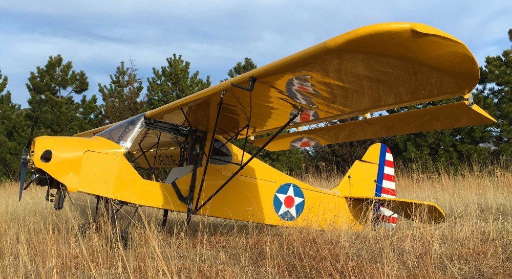
Maybe it’s time to have a look at Chipper.  Here it is:

NSM-170928-311-280-Edit

4. Chipper

I think that’s a pretty airplane.  It has a strong hint of J3 Cub design evolution, especially in the shape of the rear fuselage, tail feathers and wingtips.  It doesn’t have flaperons (they add drag), but it does have awesome flaps and droopable ailerons.  I can’t wait to try it with the slats!

The structure of Chipper is built out of mostly aluminum, including some honeycomb aluminum.  Honeycomb is amazing stuff, very light, very strong.

HC cabin

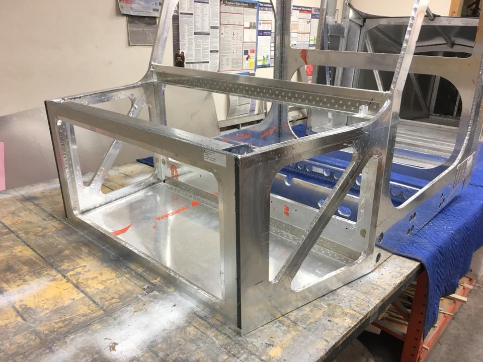
5. Honeycomb aluminum construction

We also use a lot of CNC machined billet parts in Chipper.  This gives a more pro feeling to the overall look and construction – better than welding.

CNC

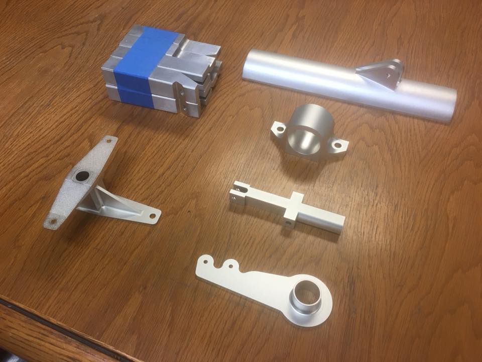
6. CNC parts in Chipper

I could talk a long time about engines.  I’ve already experienced 3 different engines in Chipper – HKS, Rotax, and ULPower.  Some builders are planning on automotive conversions (Aeroconversions, for example) while another is planning on an O200 Continental engine.

A few notes:  Rotax and ULPower are the ‘can’t go wrong’ choices.  You’ll get factory support from us; the ULPower guy is a Chipper builder and also helps with Quick Builds and builder support.  I have one customer planning on putting on a 140HP Rotax turbo conversion!
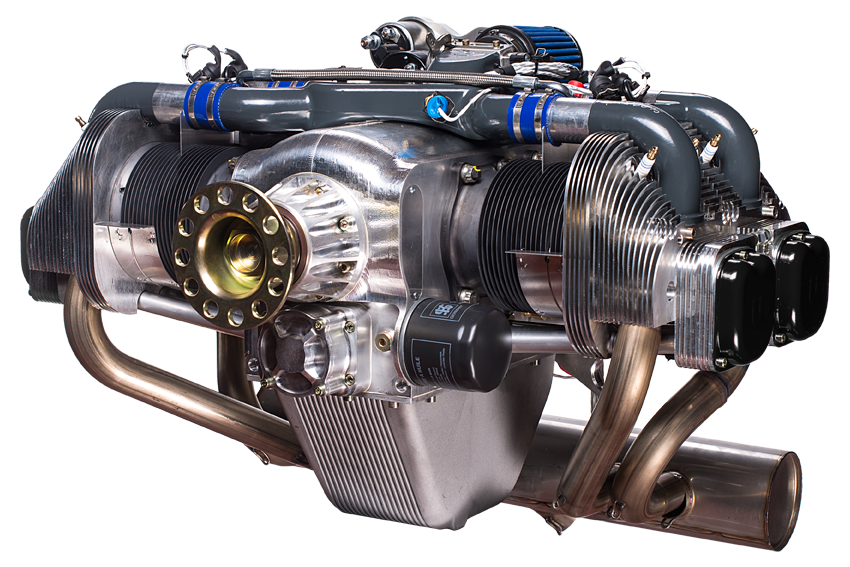
UL350iS

7. ULPower Engine

Used vs new engines are another possibility.  There is a never ending supply of used Rotax engines available, some with excellent rebuilder support.

Which to choose?  Take your time, and defer your engine selection.  Talking about engines takes us too far off point of this discussion.

For propellers, Sensenich is top of the line.  DUC Helices (French) is fantastic.  Culver props out of Missouri makes a great wooden prop.  Warp Drive are also awesome.  The selection is based on budget and who’s done what, before.  If money is no concern, just pick Sensenich or DUC Helices and be done with props.  For budget, go with Culver for wood or Warp Drive.

I recently heard that 1/3 of buying a kit aircraft is the kit, another 1/3 is the engine, and the final third is instruments.  That final third statement is baloney!  You don’t need to spend more than $2000 on instruments and radio.

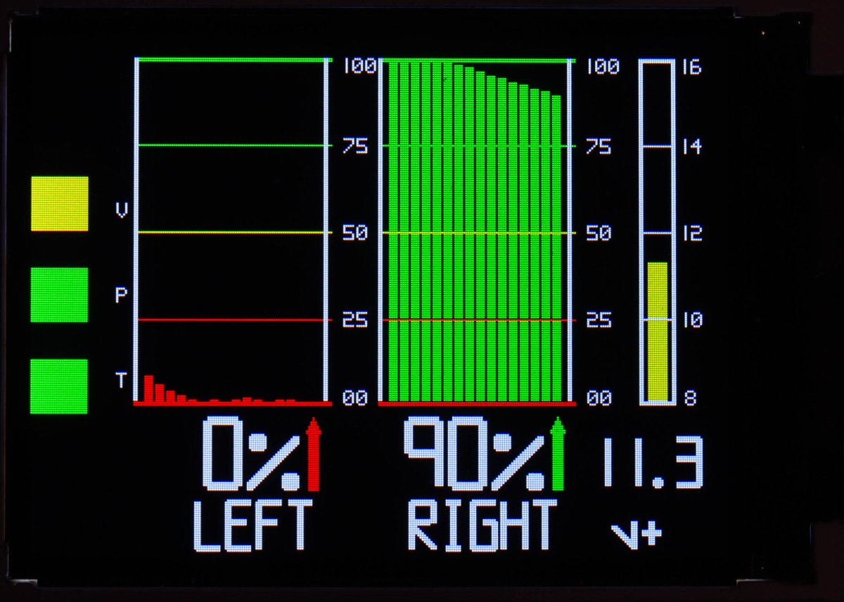
Our Radiant series of instruments have great reviews and work well; we include the airspeed / VSI / altimeter in our Chipper value purchase bundles.  With the discount, you get them for free, along with a turn coordinator.

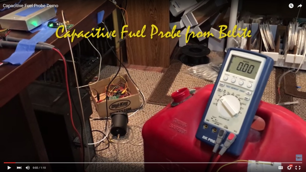
What else is needed?  Add some fuel measurement (perhaps Bingo-3 probes), along with a compass, and engine instruments to your liking.  Then add a nice 2.25” panel radio with antenna and harness.  Unless you also want a transponder, you’re done.  For navigation, I recommend an iPad App such as foreflight.  I use my cellphone with foreflight as backup.  (hmmm…. You may need an ELT as well.)

Assuming you already have an iPad, and assuming you don’t want or need a transponder, your Chipper instrument purchases, out of pocket, can be $2K.  (hmmm…. You still may need an ELT as well.)

Main Screen

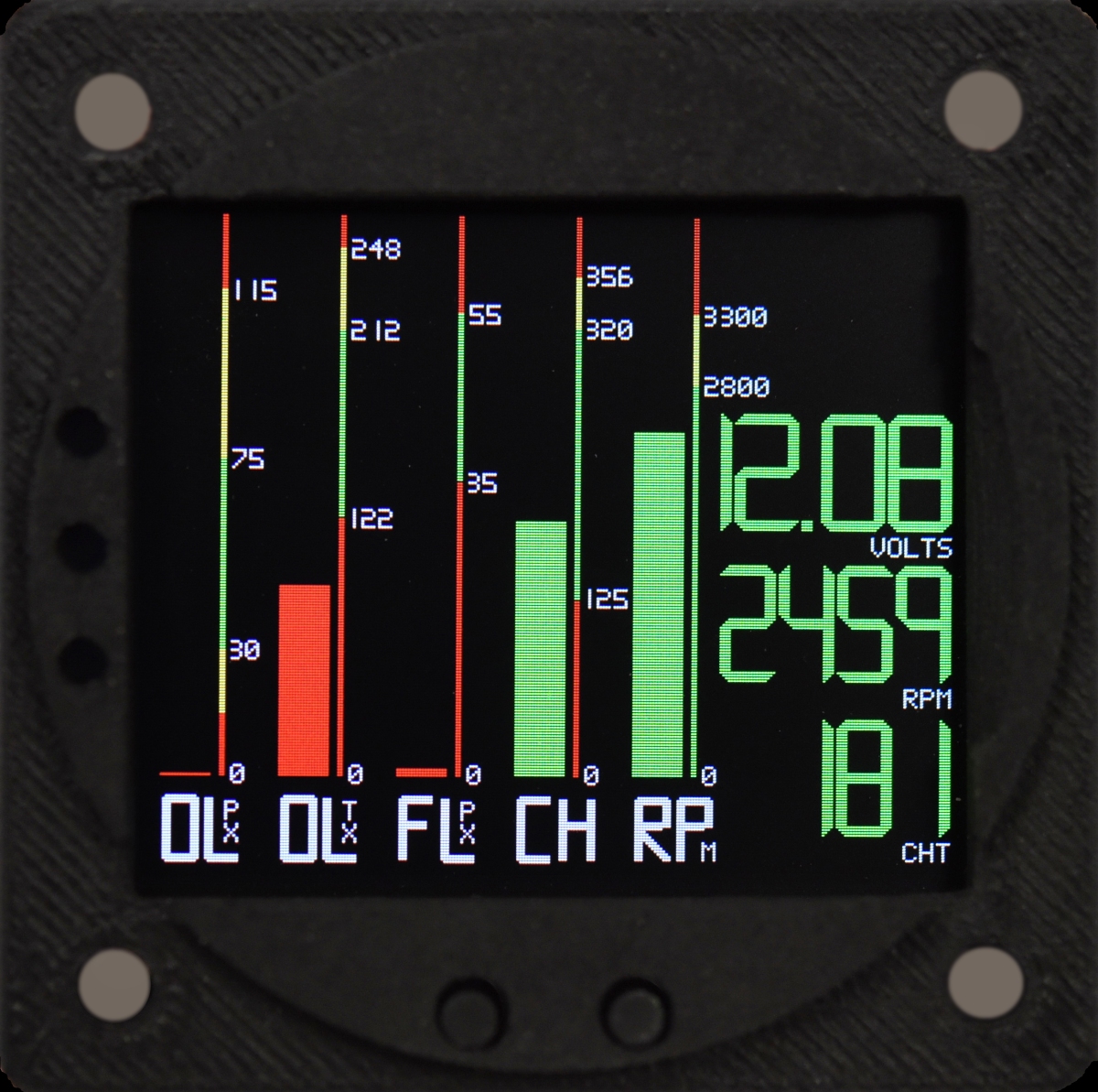
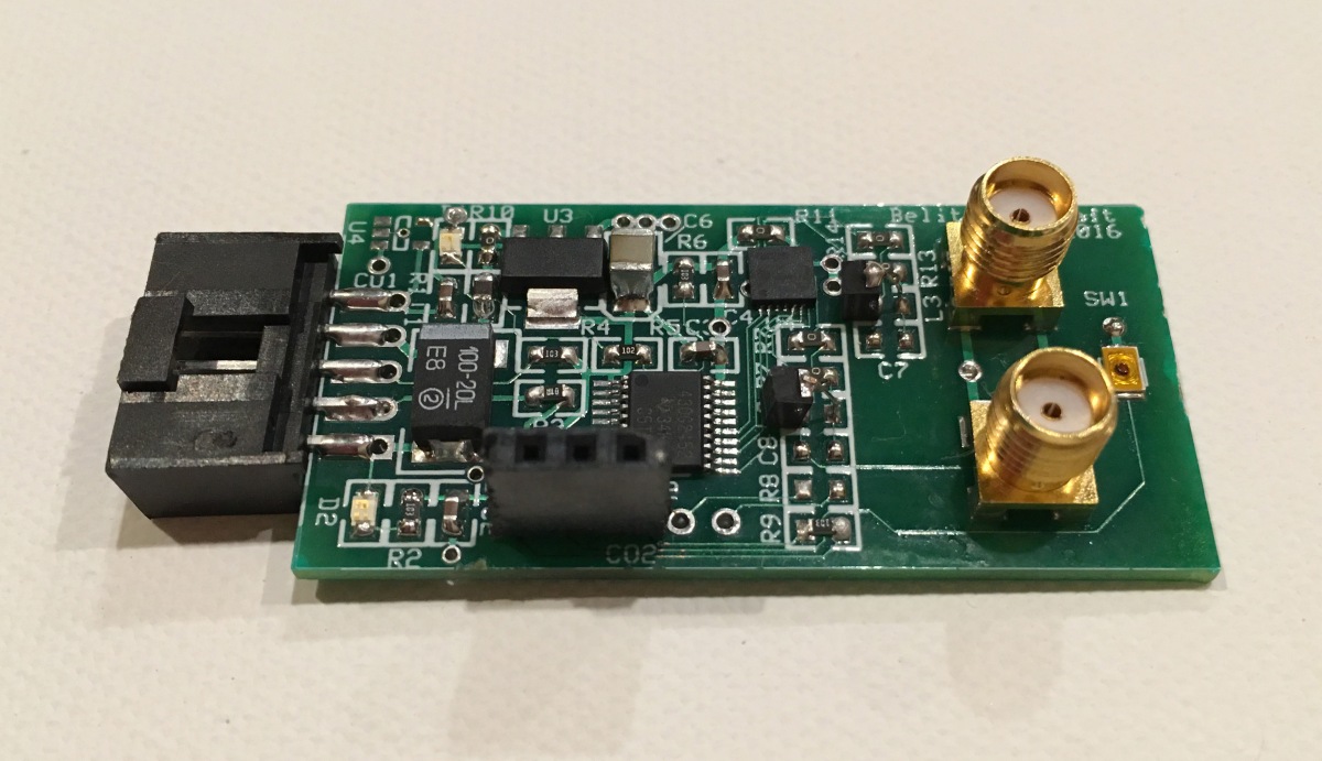
8. Radiant engine instrument

When Chipper airframe kits were first introduced at $8995, we received about 19 orders.  Sadly, many of the early customers cancelled their order, usually because they couldn’t swing the rest of the purchase, financially.  That was a good thing, because we priced the first ones at a loss, and have steadily raised prices so that we can earn a reasonable return on our investment.

Chipper remains an excellent value for the performance it provides.

Our pricing is currently $12,495 for the airframe kit, and $6,495 for the finishing kit.  Our standard airframe kit includes 34 gallons of wet wing fuel tanks.  It also includes extruded streamline struts, wheels, brakes, and a ton of CNC machined parts.  The only major options left are slats? Fabric vs metal wings? And taildragger vs tricycle gear.

The finishing kit purchase can be deferred until truly needed.  The airframe kit can be purchased in major groups.

We recommend you start with the cabin kit – it’s just $2000 + shipping/crating!

For a full featured Chipper, expect to spend $26K before you get to the engine and Firewall Forward. With a used Rotax, you can be flying quite inexpensively.  With the 80HP Rotax, you can use any autogas.

There’s a lot of other important stuff to consider:  taildragger vs tricycle; floats?; community? Etc.  Floats and configuration are buyer preference items; with STOL opportunities highly biased towards taildragger.  Community is a big thing too – we’ve got around 30 Chipper kits shipped; a great builder Facebook page (closed group) and our regular FB page as well.  It’s all been growing nicely.

Comments on Flying Characteristics

Let’s use our imagination and go around the pattern together.

I’ve already started the engine.  Our ULPower 350iS (130HP / 122HP as pitched) is warmed up and idling smoothly.  I’ve already done our mag check; I’ve scanned the engine instruments and verified that all temps and conditions are green.  I selected a full fuel tank; the pattern is empty; there’s an 8 knot breeze straight in our face, straight down the runway.  FWIW, the sky is blue and an awesome day to be up in the air.

Taxiing from the ramp to the numbers is non-eventful; steering is easy with the differential toe brakes.  The nose angle is high because of our long gear and 22” tires.

For this flight, we’re near gross weight.  That’s OK.

I’ve selected 10 degrees of aileron droop and 30 degrees of Fowler flaps.

Applying power, the tail comes up nearly immediately and I’m using the rudder and toe brakes to keep everything tracking straight down the runway.  150’ from go, I pull back on the stick and we’re airborne, climbing out at a steep angle.  I look over at you and I see you grinning.

With the breeze on the nose and the cool temps, we’re about 500’ off the ground as we approach the end of the runway.  Another 10 seconds of climb, I reduce power and turn crosswind.  The plane insists on more climbing, so I reduce power again.  As the nose angle lessens, the speed starts to go up.  We’d seen about 50mph in the climb.  Since we’re going around the pattern, I leave all of the flaps and ailerons hanging, managing altitude by power and ensuring that I don’t overspeed this slick plane.

That’s how we go on downwind – keeping the plane down and managing our power to keep the speed from going up.  Abeam the numbers, I bring the prop RPM back to no more than 1900.  A moment later, I’m turning base leg.  I glance over at you – your still smiling.

Our engine is fuel injected, so there’s no carb heat to mess with, but I do check the mags out of habit and also glance at the fuel gauge, confirming that I’m still on a full tank.  Somewhere, my complex training kicks in and GUMP moves through my head, unnecessarily (Gasoline, Undercarriage, Mixture, Propeller).  I’ve got gas, my undercarriage is ‘down and welded’, I don’t have mixture, and I don’t have a propeller control.

Turning base, I reduce power to 1400 RPM, and Chipper starts to descend.  I’m managing speed to about 55mph.  I might have to pull back power just a smidge to keep the descent on the pronto, while keeping an eye on speed.

I like the flaps and the aileron droop settings, I’ve got to keep the nose up a bit so that Chipper doesn’t start going too fast.

Turning final, I’m nearly at idle power, and I’m content with the descent rate.  I’ve heard that some STOL aircraft ‘descend like a brick’ in the absence of power, but Chipper isn’t one of them.  It floats down.  I really have to work hard (mentally) to convince myself to keep dialing in up elevator, and the nose up angle feels a little high – but that’s just a feeling.  It is, in fact, correct, and the nose is high, and it should be.  I am thankful for elevator trim.

Over the numbers, my speed is indicating around 45mph.  With the wind on the nose, our groundspeed is already in the mid-30’s, and I’m looking at you again (just for a long glance).  I can tell that you’ve never felt a landing speed this slow, or if you did, the engine still had a lot of power dialed in.  This is, different.

Entering ground effect, I continue to pull back on the stick for a perfect 3 pointer.  I push on the toe brakes just hard enough to stop us quickly, and we’re done moving in around 250 feet.  With a little practice, I could do better; hopefully a lot better.  I still have some learning to do.

We taxi back to the ramp and shut the engine down.  You and I spend the next two hours talking about flying.  I tell you about flying to Idaho, and also to Alaska.  You tell me how you’ve always wanted to do things like that.  I talk about pacing, education, instruction.  We talk about engines for a long time.  You talk about your concerns in the building process.  I talk about my years of fun working with ultralight aircraft.  I invite you to come to a builder seminar.  I also invite you to watch this video: (click on it)


Epilogue

When you build an airplane, you need it to satisfy your needs, and your needs may be very complex.  The process of due diligence helps you figure it out.  Ask questions, haunt forums, go to Airventure; Sun N Fun; and other regional shows.  Watch.  Get a ride, if you can.  Read reviews.

I’d be delusional if I thought Chipper was the airplane and building experience for everyone; it simply isn’t.  Once in a while, I think about how nice it would be to get to Denver in less than 2 hours, so I can visit my daughters, which I can’t do in Chipper.  I need a 200 knot airplane to do that.

Then I think about going fishing at Gaston’s, in northern Arkansas.  It has a grass strip, and the trout fishing can be fantastic.  Airnav.com says it is 237 nautical miles from my home field; I’m likely to catch a tailwind on the way down.  I flight plan for 2:20 takeoff to landing in Chipper, and I’ll burn about 12 gallons of gasoline.  The equivalent car drive would take 6 hours; not including stops.  Gastons becomes a very reasonable weekend (or overnight) destination in Chipper, and is way faster than driving.  I don’t need to refuel when I’m ready to start home, as I started with 34 gallons of gas.  I make it home with reserve to spare.


Digital Tachometer / Hour Meter

Looking for a great, simple, inexpensive digital tachometer that works with just about any gas engine?  You’ve found it!  All the technical details are below, and you can purchase on our webstore anytime:

http://www.beliteaircraftstore.com/tachometer/

The Digital Tachometer / Hour Meter is a general purpose, ignition spark lead based instrument.  Mount it anywhere using the included Velcro patch.  Works with two or four stroke engines; also includes a job (oil change) interval countdown timer.

Radiant Tach Green Background

FEATURES & SPECIFICATIONS

  • Small size, 2 5/8” x 1 3/8” (67mm x 35mm)
  • Easy Installation, usewith Velcro patch anywhere (included)
  • Standard coin battery power is included (CR2032)
  • Basic Interface board available separately, allows +8 to +32v power supply and LED capable signal output.
  • 60” cable harness – standard (1.5 meter)
  • Crisp LCD display
  • Green backlight
  • IP65 water rating
  • ROHS compliant

OPERATION

  1. Stroke setting – press the MENU button several times until the current stroke setting appears.  Default is “1P1R”.  There are eight options, and they include:
  • 1P1R – 1 spark per 1 revolution
  • 2P1R – 2 spark per 1 revolution
  • 3P1R – 3 spark per 1 revolution
  • 4P1R – 4 spark per 1 revolution
  • 6P1R – 6 spark per 1 revolution
  • 3P2R – 3 spark per 2 revolution
  • 5P2R – 5 spark per 2 revolution
  • 1P2R – 1 spark per 2 revolution

To change, hold the MENU button down until the display starts to flash.  Then touch the SET button until you’ve rolled around to your preferred setting.  Just wait a few more seconds, and the unit will go back to the TOT main screen.

  1. Refresh rate setting – press the MENU button several times until the current rate setting appears. Default is “0.5”.  There are two options, and they are:
  • 5 – Screen refreshes every half second
  • 0 – Screen refreshes every second

To change, hold the MENU button down until the display starts to flash.  Then touch the SET button until you’ve rolled around to your preferred setting.  Just wait a few more seconds, and the unit will go back to the TOT main screen.

  1. RPM display – the current RPM is displayed when the engine is running. When the engine stops running, the TOT main screen is shown with updated time.
  2. MAX RPM display – press the MENU button several times to enter into the MAX RPM display screen. You’ll see the MAX RPM since the engine was turned on.
  3. RPM alert setting – Press MENU several times into the alert setting screen. The default is 8500 RPM.

To change, hold the MENU button down until the display starts to flash.  A short press on the MENU button will decrease the value.  A short press on the SET button will increase the value.   Just wait a few more seconds (after you’re done making changes), and the unit will go back to the TOT main screen.

When the actual RPM of the engine is higher than the RPM Alert value you set, the RPM alert icon will flash, along with the actual RPM.  It will flash 5 times every half second, then stop for 3 seconds.  The pattern repeats until you reduce RPM.

  1. Total hours TOT screen – When the engine shuts down, the LCD interface will show total TOT time.
  2. Backlight control – touching either the MENU or SET button briefly will turn on the backlight for two seconds.
  3. Job Timer screen – Press MENU two times, the screen will display the JOB timer. This is the current session time, since the engine started.

To zero, hold the MENU down for several seconds.

  1. SVC service time display – Press MENU three times, and the LCD interface will show the service time. This is a countdown timer.  It is typically used for oil change advisories, or for 100 service interval reminders.  Use it to suit your preference.

To change, hold the MENU button down until the display starts to flash.  A short press on the MENU button will decrease the value.  A short press on the SET button will increase the value.   Just wait a few more seconds (after you’re done making changes), and the unit will go back to the TOT main screen.

The allowable range of values is 0 to 200 hours.

When SVC is flashing, press MENU or SET to clear.

After SVC is cleared, it enters into the next countdown cycle automatically.

  1. Battery level – A battery icon in the upper right hand corner of the LCD interface shows the current battery level. It shows a range from four bars down to empty (no bars). It will flash when the battery needs replacing.

Bingo3 Fuel Warning Sensor

“Bingo3 Fuel Sensors – an ideal companion to fuel flow sensors”
A brief WhitePaper by James Wiebe, CEO, Radiant Instruments
September 19, 2018

Modern experimental and certified general aviation aircraft commonly use fuel totalizers with fuel flow sensors in order to accurately gauge the amount of fuel used by the aircraft. When coupled with a known value of fuel prior to flight (for instance, by filling the aircraft or by visually examining the fuel level), the pilot has a very accurate indication of fuel left in the tanks at every point in the flight.

Additional information provided by a fuel probe of some sort usually fills the complete information required for safe flight. But that’s the problem – fuel probes keep running into trouble.

Bingo3 is an alternative to fuel probes which provides point certainty as to fuel level. Bingo3 is a fuel probe which senses the presence or absence of fuel at its installation point. Therefore, Bingo3 can be installed at whatever point the pilot wants a firm notification as to fuel remaining.


Why do it this way? Here’s some answers:
• Longer fuel probes are unavailable or very expensive.
• Older resistive probes are mechanical and wear out, costing time and money. They often simply work very poorly. Replacements are expensive.
• Capacitive probes also have a high failure rate, due to shorts, quality, and water contamination.
• All high quality fuel probes are expensive. Bingo3 isn’t!
• In our opinion, existing fuel probe technologies can’t provide the fuel point certainty that Bingo3 provides.

Here are two use cases:

A) Wing tank. In this scenario, Bingo3 is installed so that it warns the pilot when there is 45 minutes of fuel remaining in the tank. Bingo3 is shown installed on the side of the tank, and the height above bottom represents 45 minutes of fuel reserve in cruise flight. The actual positioning of the Bingo3 is determined by the aircraft owner’s desired warning point. Want more time? Place it higher. Want less of a warning? Place it lower. Want multiple warning points? Put 2 or more Bingo3 products in each tank, at different levels. Use the inboard panel of the tank; or use the outboard panel of the tank (for even earlier warning). Bingo3 does not care about its mounting position.

B) Header tank. In this scenario, Bingo3 is placed at a location where the header tank is no longer full. Therefore, the pilot has a few minutes warning (EG, change tanks or land) before fuel is exhausted. A typical installation spot in a header tank would be 80% of full capacity.

As mentioned, Bingo3 doesn’t care about mounting position. It uses an infrared emitter / sensor pair which detects the presence or absence of fluid on its facet surfaces. It is very small, easily installed, and very reliable. The following diagram shows various mounting positions and also invites usage of Bingo3 in other applications. Consider using Bingo3 at a top mounted location for showing full fueling.

Conclusion: Bingo3 is an excellent, easily installable, inexpensive device which provides critical fuel level information to pilots.

Links:

http://www.beliteaircraftstore.com/bingo-3-liquid-detector/


I’ll Pound Y’all

Let’s get wingfoil technical, OK? The photo shows a lift analysis of a#SkyDock airfoil at an attack angle of 4 degrees. At this angle, we’re generating a coefficient of lift of 1.39 with a drag of .0144. This produces a Lift / Drag ratio of 96.73.

wingfoil_0flap_4alfa

In order to generate a lift of 660 pounds (#SkyDock gross weight); the induced drag from the entire wing is 7 pounds.

(Real world values vary substantially… topic for another post…)

Now let’s get practical and estimate in-flight speed to exactly carry the airplane at a 4 degree angle of attack. How fast does the airplane have to go to balance lift & aircraft weight exactly?

Let’s do this in English units, not metric.

It’s easy. Using the lift formula, which looks complicated but isn’t:

Lift = (0.5) ρ v² A Cl

ρ = air density;
v = velocity;
A = Area of wing;
Cl = Coefficient of lift;

We want to solve this equation for velocity. So the equation is rearranged as follows:

v = ((Lift * 2) / (ρ * A * Cl)) ^ 0.5

And now we solve.

Lift = 660 pounds (SkyDock @ gross weight)
ρ = 0.074887 pounds per cubic foot
A = approximately 120 square feet
Cl = 1.39

The answer is … 10.28 feet per second or 7 mph.

Oh My! that’s not correct! NOT EVEN CLOSE!

The problem is the we have solved without taking into account the conversion of force into pounds. Our result should have been intermediately calculated using the relatively obscure unit of ‘poundal’, with a consequent conversion to pounds.

It kind of reminds me of my youth, when I’d be avoiding some bully in the hallway, and he’d ‘pound y’all’ if I got in his way. Different situation… I digress.

A poundal is a unit of force, unlike the bully, who was a unit of terror. At acceleration of one gravity, it is equivalent to a pound using this formula:

1 poundal = 0.031081 pounds.

Fixing the formula from above,

v = ((Lift * 2) / (ρ * A * Cl * 0.031081)) ^ 0.5

And solving one more time using the same variables

Lift = 660 pounds (SkyDock @ gross weight)
ρ = 0.074887 pounds per cubic foot
A = approximately 120 square feet
Cl = 1.39

The corrected answer is … 58.31 feet per second or 40 mph.

Now we know: A SkyDock flying at 40mph with zero flaps and angle of attack of 4 degrees will generate exactly the lift required to balance offsetting gross weight of the airplane.

The author of this post, James Wiebe, has a degree in Math from Tabor College, Hillsboro, KS.

Wing Spar Load Test on SkyDock

Hi K.,

This slideshow requires JavaScript.

We ran our negative G load test today on our SkyDock prototype.  As the loading was far in excess of the anticipated flight load, this may be considered an ultimate load test.   It was successful with two glitches.

Assumptions:
Gross Weight:  660 pounds
Weight of wing structure 62.5 pounds per wing (outboard of cabin).
Zero Fuel Weight:  570 pounds (90 pounds of fuel; 45 pounds per wing in outboard section).
Testing to 3.8G’s, negative load.
Each sandbag weighed.
Methodology:
1)  Plane was loaded generally in accordance with spreadsheet.  See attached.
2)  Conservative methodology:  stations 0 and 1 weight loads were placed at stations 2 and 3; this increased load on wing.
3)  Glitch 1:  Rivet structure showed signs of failure on both sides on front of “D” cell strap assembly.  Rivets pulling out of carbon fiber “D” cell.  Will be redesigned.
4)  Glitch 2:  center test support structure was placed under carbon fiber in such a way that carbon fiber skin was deflected upwards in tension into internal foam ribs, but just on one side of support structure.  This caused slight permanent compression into foam inside.  Carbon fiber skin is unharmed.  Repair is easy; just inject some expanding foam at affected area.  If / when test is repeated, test support structure will be completely under spar hard points.  This is a testing failure, not a structure failure.
Thanks for your assistance in analyzing the design of this wing.  It’s always fun to see a light thing hold a lot of weight.
Some comments on deflection:  we measured approximate deflection of 4 inches at station 9.5; (this is where we had our safety support stand).  Each section of the wing has a different moment of inertia; the center section is obviously the strongest.  The outboard section has a much lower value; and the third would be on the massive spar strap that connects the outboard and inboard together.  I don’t think we’ve calculated how these play together for predicting deflection; but in any case, the wing is acting like it has an average moment of about 8.  That’s pretty impressive, as I recall the moment of the outboard sections was designed to be around 4.2; the improvement is no doubt because of the carbon fiber bonded to the top and bottom of the spars.  What do you think?
Best Regards
James

Breakthrough Capacitive Fuel Probe

Product Preview:  Belite Capacitance Fuel Probe

Last Revised March 8, 2016

http://www.beliteaircraft.com

ALL INFORMATION PRELIMINARY AND SUBJECT TO CHANGE

Cap Probe

Capacitive Fuel Probe controller module.  Functional prototype shown.  Case not shown.

Background:

Probes for fuel tanks have often used the principal of “capacitance” to determine the level of fuel within the tank.  These probes are usually constructed of a thin conductive center probe surrounded by a liquid permeable sheath and a grounded jacket.  Commonly available in lengths from 12” to 24” (or longer), these probes suffer from the following problems:

  • Although many claim to be bendable, in our experience we’ve found them to frequently short and fail when bent.  Bendability is a requirement to fit through access holes and at a diagonal positioning from the hole to the bottom of the tank.
  • Presence of minute amounts of water within the fuel may cause these probes to fail. Water is a very good conductor of electricity (specifically when non-pure or contaminated.)
  • Calibration of capacitance probes is affected by changes in the dielectric quality of the fuel in the tank. Specifically, a mix of AvGas with autogas, or a mixture of alcohol within that autogas will cause capacitive probe readings to fail.
  • We believe that almost all capacitive probes on the market are designed with older technology circuits that are less immune to high electrical noise environments, such as what is found in aircraft. While this is a more subjective claim, we have solid foundation in making new claims of noise immunity with our new design.
  • Most capacitive probes require intrusive, large holes in the top of the tank in order to mount the probe puck.


Belite’s new Capacitive Fuel Probe Solves Problems

Our new probe resolves these issues and offers substantial benefits.  In particular, the probe has the following features:

  • The probe is a flexible wire assembly. It may be routed from one corner of the tank to the opposite corner, and held in place at the far corner using a simple mechanical hook.  It does not care what path it takes, as long as that path is surrounded by the fluid to be measured.  It also does not care (within reason) the length of the wire within the tank, and will accommodate any length between 6 inches and 40 inches (one meter).    The wires are jacketed with Fluorinated Ethylene Propylene (FEP).  This material is amazing.  Quoting one of the manufacturer’s websites:

For instance, in the automotive industry, chemical transference is often needed to deliver vital fluids throughout a vehicle’s complex engine. With this in mind, the flexibility and high working temperature characteristics of fluoropolymer tubing can provide custom applications in long lengths on a variety of vehicles.

Since fluoropolymer tubing is a fantastic insulator, it can offer electrical insulation and chemical resistance that makes it a great splicing aid for high continuous service temperatures in corrosive environments.

Source:  http://www.fluorotherm.com/the-different-applications-variations-of-fluoropolymer-tubing/

  • Our probe will not fail in the presence of water. (Water will affect the reading, but the unit will continue to function in an accuracy degraded mode.)
  • Our probe electronic module includes a calibration button which is used to set the Empty and Full position of the fuel tank. This button may be optionally routed to a pushbutton switch in the cockpit, so that the fuel probe may be recalibrated to Full after the tank is filled.  Therefore, full position calibration is automatically recompensated for type of fuel in the tank – 100LL, AutoGas, with or without alcohol.
  • This probe was designed using an integrated circuit with a novel tuned inductive filter on the probe input. This has demonstrated a great deal of noise immunity.
  • The wire assembly may exit the tank via a vent hole or any other hole. In a good tank design, this would be in that portion of the tank reserved for fuel expansion as the fuel warms up on a hot day.

Cap Probe Wire Module

Prototype wire assembly.  Not final shipping version, but a pretty good representation.

How does this new fuel probe work?  What are its features?

  • The design uses a very stable temperature compensated capacitive oscillator in conjunction with a tuned inductive filter. As fuel surrounds the wire probe, the capacitance changes.  The circuit is capable of resolving very small changes in fuel height and converts this to an output voltage, which is linear to the fuel level.  The more fuel, the higher the voltage.
  • The circuit is compatible with any type of gasoline, alcohol, or jet fuel. Kerosene is just fine.
  • The fuel probe unit provides a linear +5 volt output, compatible with almost all modern fuel display gauges and EFIS displays.
  • We specifically recommend our new RADIANT fuel gauge as a companion to the fuel probe.  While the product preview document you are reading is about the Fuel PROBE, we’ll interject for a moment and show you a few photos of our RADIANT fuel GAUGE.  Here is a screen shot of the fuel gauge:

Image2

Screen shot of RADIANT fuel gauge.  Left tank is empty and right tank has been drawing down fuel for approximately 10 minutes.  
We recommend this RADIANT fuel gauge for these reasons:  it has a great 2 minute sloshing filter built in; it shows 15 minutes of fuel trend history, and it is a full color, it is nearly weightless, it is sunlight readable display.  $200.

Now, back to the fuel probe:

  • The controller board on the fuel probe has one switch. For calibration: after powering up, press it quickly to set the “low” fuel point.  After filling with gas in the tank with the probe, press it longer (a few seconds) to set the “high” fuel point.
  • A remote switch may be mounted in the cockpit. Pressing it will reset the “high” calibration point.  To avoid accidental high point resets, this requires a five second touch on the switch.  This allows automatic recalibration after every tank filling.
  • For hard core techies: the unit’s connector also provides a +5v regulated output.  This allows a differential analysis of the signal level, as the output DAC is technically ratiometric to the +5V supply.  If you understand that, you’re an electrical engineer.  If you don’t, just ignore it.
  • For hard core OEMS: this product is also available with digital RS-232 serial output, periodically broadcasting the fuel level at 9600 baud.  This allows direct digital attachment to a variety of EFIS systems, assuming support from the EFIS vendor.


What does the Belite Capacitive fuel probe cost?  When is it available?

  • The unit is priced as follows: Unit + 6” probe — $200; Unit + 12” probe — $210; Unit + 40” (1 meter) probe — $250.  Custom lengths are available; contact factory.  Includes electronic unit in small case; wire probe of 6”, 12” or 40” length; power connector and pigtail harness; short coaxial cable to connect together probe to module.
  • First shipments are projected in Q2.
  • Orders received between March 8 and April 30 receive a 25% discount. In order to reserve your delivery position and receive this discount, we must charge your card at time of order.  All such orders are expected to ship by May 30.
  • A similar special is available on our RADIANT fuel gauge.   Orders received between March 8 and April 30 receive a 25% discount. In order to reserve your delivery position and receive this discount, we must charge your card at time of order.  All such orders are expected to ship by May 30.

Want to see a demo video?  Navigate here:

https://www.youtube.com/watch?v=9gQ1bJECmBo&feature=youtu.be

Cap Probe Demo Video Screen Shot

UltraCub Rib Construction — Aluminum ribs with cap straps

If you are building aluminum ribs (or aluminum / carbon fiber strips), the top and the bottom “T Strips” have to be glued on with 2216 or similar epoxy after they are riveted in place.

2216 is a 3M epoxy which is specified for use with aluminum bonding.  Surfaces must be scoured clean (eg,: 180 grit), then cleaned with acetone, before a liberal fillet of 2216 is added on all sides.

Tape was used to stabilize the strips while glue was applied and setting.

The tip and root rib get a square aluminum tube reinforcement.

We also recommend a 5″ vertical piece of angle on each rib, to prevent vertical crushing.  (Not shown, will provide pic soon.)

Rib Construction

Rib Construction

Root and Tip Rib reinforcement Root and Tip Rib reinforcement-2

How to cook trout in the wild, with wine and Tabasco.

In today’s cooking lesson, we’re going to learn how to prepare James’ amazing!!! mildly hot trout recipe.

The very first thing to do is to clean your trout.  It’s easy — cut off the head, gut them, clean out the innards, and leave the skin on.  The skin will come off easily while being cooked, so don’t worry about it.

Then, retreat out of the wild into a cabin with a stove and a frying pan.  This is a very important step — don’t get it wrong.

Start the preparation by melting a half stick of butter or margarine in the frying pan.  I used margarine, but you should use butter.  Really.

Cooking

Melting a half stick of butter in a frying pan, over low heat.

Once that has melted and is lightly bubbling, insert the trout into the pan.  It is helpful if the tail sticks slightly over the edge — this will help impress your friends.

Cooking-2

Trout beginning to cook in bubbly butter. The trout tastes best if the tail sticks slightly over the edge of the pan. No, I’m not explaining why that is so.

The next step provides some extra flavor — throw in 3 or so ounces of your favorite red wine.  The best wine is a cheap red, straight from Santa Clara, CA.  (Inside joke.)

Cooking-3

Red wine in the pan.

Now, another critical step.  Locate an abused old pizza pan, such as shown in the following photo.

Cooking-4

Abused old pizza pan.

Place the pizza pan over the frying pan.  You should be able to hear the butter / wine mixture lightly bubbling away.  Don’t set the heat too high — a low heat is fine.  (The stove I used in the cabin worked fine with the dial set to 2 (out of 10.))

Cooking-5

Abused pizza pan is now covering frying pan and allowing trout to simmer in the wine / butter mix.

Allow 6 minutes to pass.  Then remove the pizza pan.  *Flip the trout using a spatula or fork.*  Your trout will now look like this:

Cooking-6

Half cooked trout.

Insert a knife under the skin; peel off the skin.  It’s fairly easy to do.

Cooking-7

Removing the skin off the half cooked trout.

Cooking-8

Now the skin has been removed from this side. It’s starting to look very tasty — but wait! It’s still only half cooked.

Sprinkle four drops of Tabasco onto the half cooked fish.  If you wish, you may spread the Tabasco over the side of the fish.  Also add salt and pepper to your desired sodium level at this time.

Cooking-9a

Tobasco drops have landed. Also salt and pepper to taste.

RECOVER the pan with the pizza lid and allow to cook on very low heat for 6 more minutes.  AFTER six minutes have passed, turn the heat up to a medium / high number.

Cooking-10a

BRIEFLY turn up the heat!

After about 45 – 60 seconds at the higher heat, remove the fish from the pan.  With a little effort, you can leave the bottom layer of skin (which you just slightly seared) on the bottom of the pan.

Then, transfer the fish to fine china.  Consider adding a side of Lay’s Sweet South Heat Barbecue potato chips — a truly excellent choice.

This meal pairs well with a ridiculously cheap red wine in a plastic tumbler.

Cooking-11a

James’ hot trout with hot potato chips and red wine in a plastic tumbler.

Cooking-12

Bon appetit! The trout flakes off the bones — and it was truly delicious.

From swimming in the stream to eating it at the table, this took about 75 minutes or less.  That’s fresh trout.

Let me know how this turns out for you.  Bon appetit!